REALTIME AUGMENTED –
Arenas are buzzing places when a game is on but the fall out spaces which are underneath the seating tiers seem to be dead. If such places are given public space approach by revitalizing the area would bring life to these spaces. Revitalizing by adding market spaces, restaurant & lounges or interactivity can light up the dead spaces. Engaging the visiting crowd in the live game without them have to own a ticket can be one interesting thing. The real time visuals when abstracted in a pixelated form governed by the activity of crowd using areas beneath the tiers and the movement of players on the field can arise responsive form of architecture.
Concept –
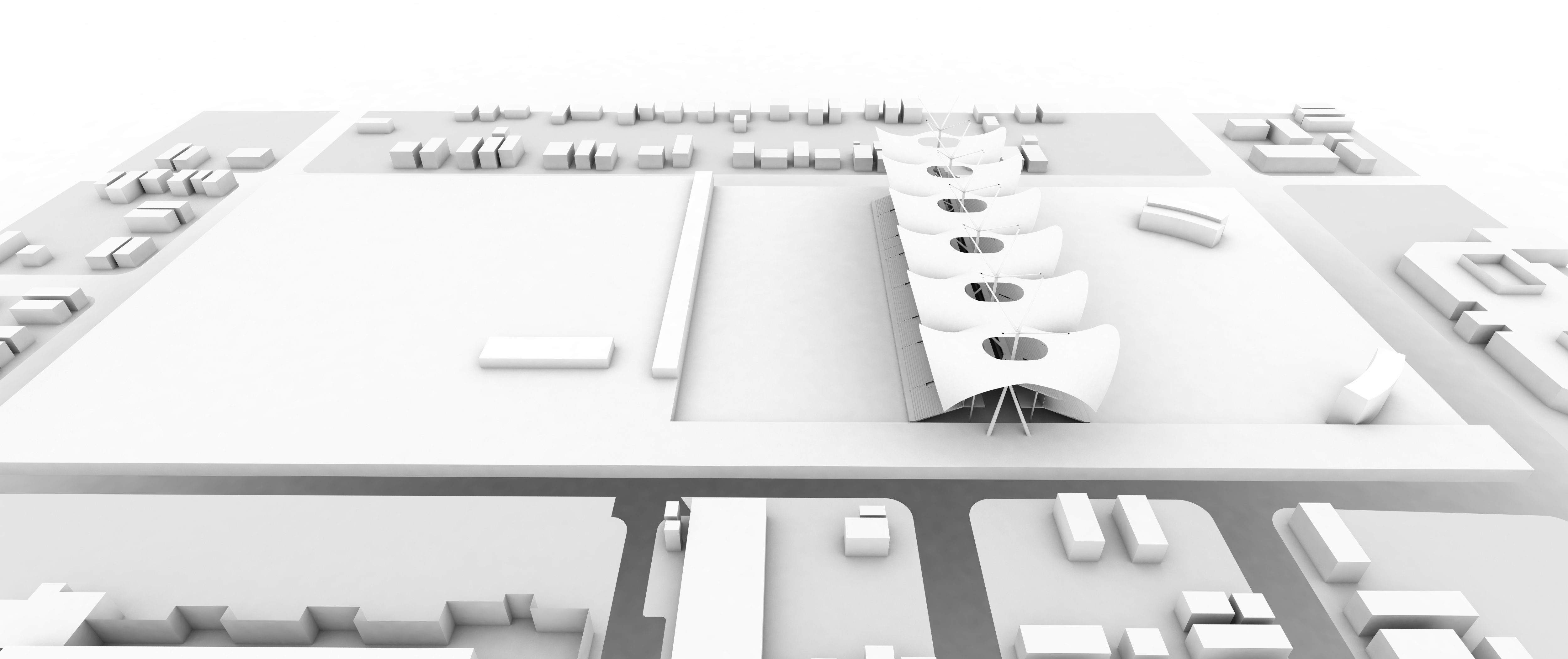
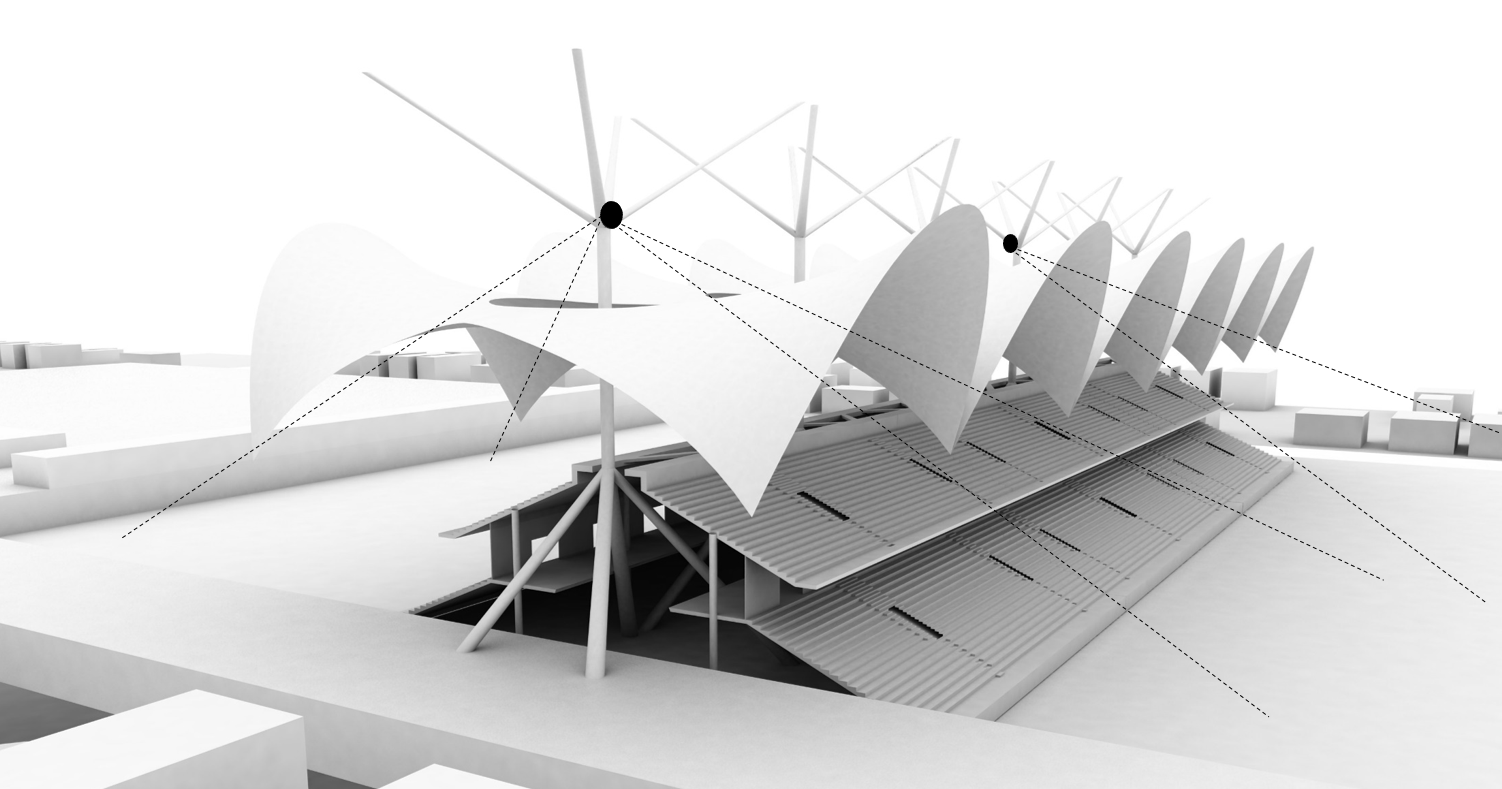
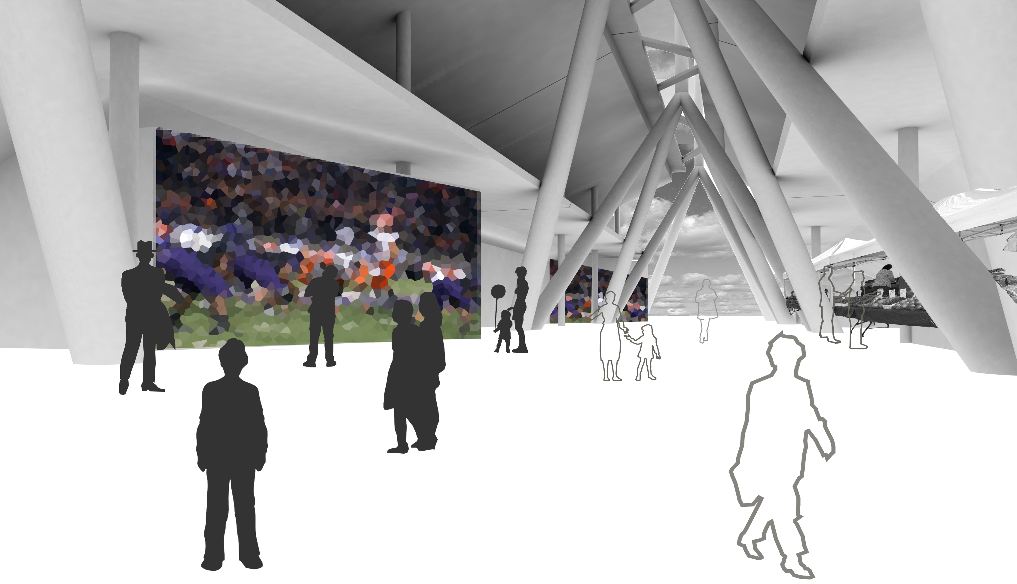
The Arena design is about engaging the city with the play fields and surrounding spaces visually and physically. The crowd visiting the arena for game is evenly given seating and lounge spaces. At the same time, the fallout spaces of arena are used as spaces of transit and recreation. These spaces are particularly the ones beneath the seating tiers. The space is designed in a manner it acts as a through way for the pedestrians connecting the two ends of the site and also it serves as a recreational space housing various activities and functions like restaurants, lounges, gymnasiums and market place etc. The idea is to serve the passersby the feel of the actual game happening in the arena by creating a visual narrative of the live game. Design conception is about the idea of circulation within a semi enclosed entity with various visual and physical spatial experiences.
Design Overview –
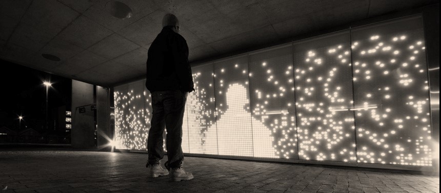
The movement of players will engage with the digital material physically and the interactive wall would be articulated by this playdata. The outside space would be augmented with virtual reflection of inside physical game. The idea is to capture the movement of players and portray those as abstract interactive images on the walls beneath the seating tiers. This would give the crowd using the throughway to indirectly engage in the live game.


Stage 1 –
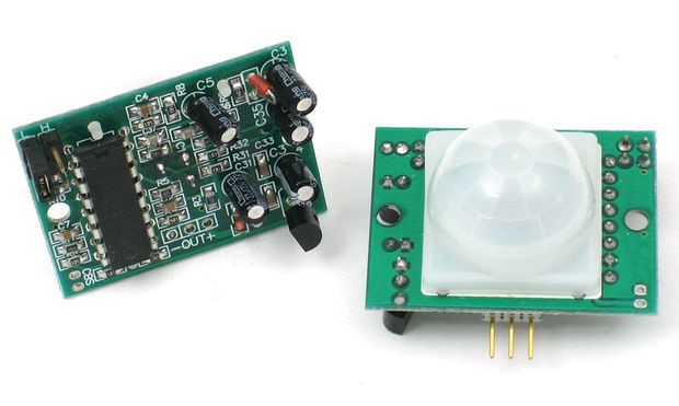
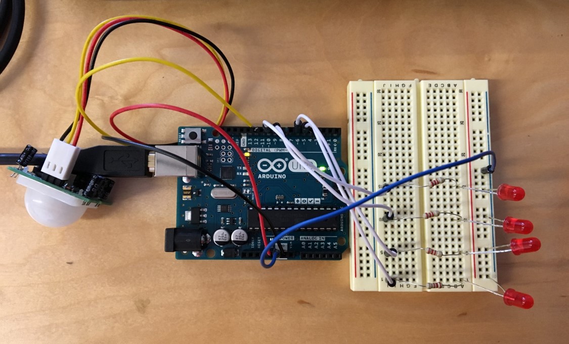
The idea was to capture the movement of players with the PIR motion sensor. The movement of players sensed through the motion sensor giving out results from Arduino uno in the form of interactive LED wall which would be digital visual for the public spaces beneath the seating tiers.

Arduino Uno Assembly –
PIR motion sensor
Output –
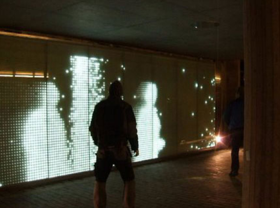 Image Source – ersteswienernachtentwerfen
Drawback- PIR motion sensors give reception only around 10′-15′.
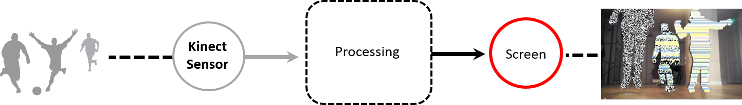
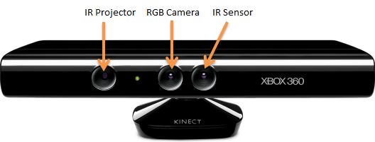
Stage 2 –
At a later stage the possible option was to capture the movement of players with the Kinect motion sensor for depth images and using processing it would give the output in the form of interactive images on the walls beneath the seating tiers.
Output –
 Image Source – rhizome.org
Stage 3 –
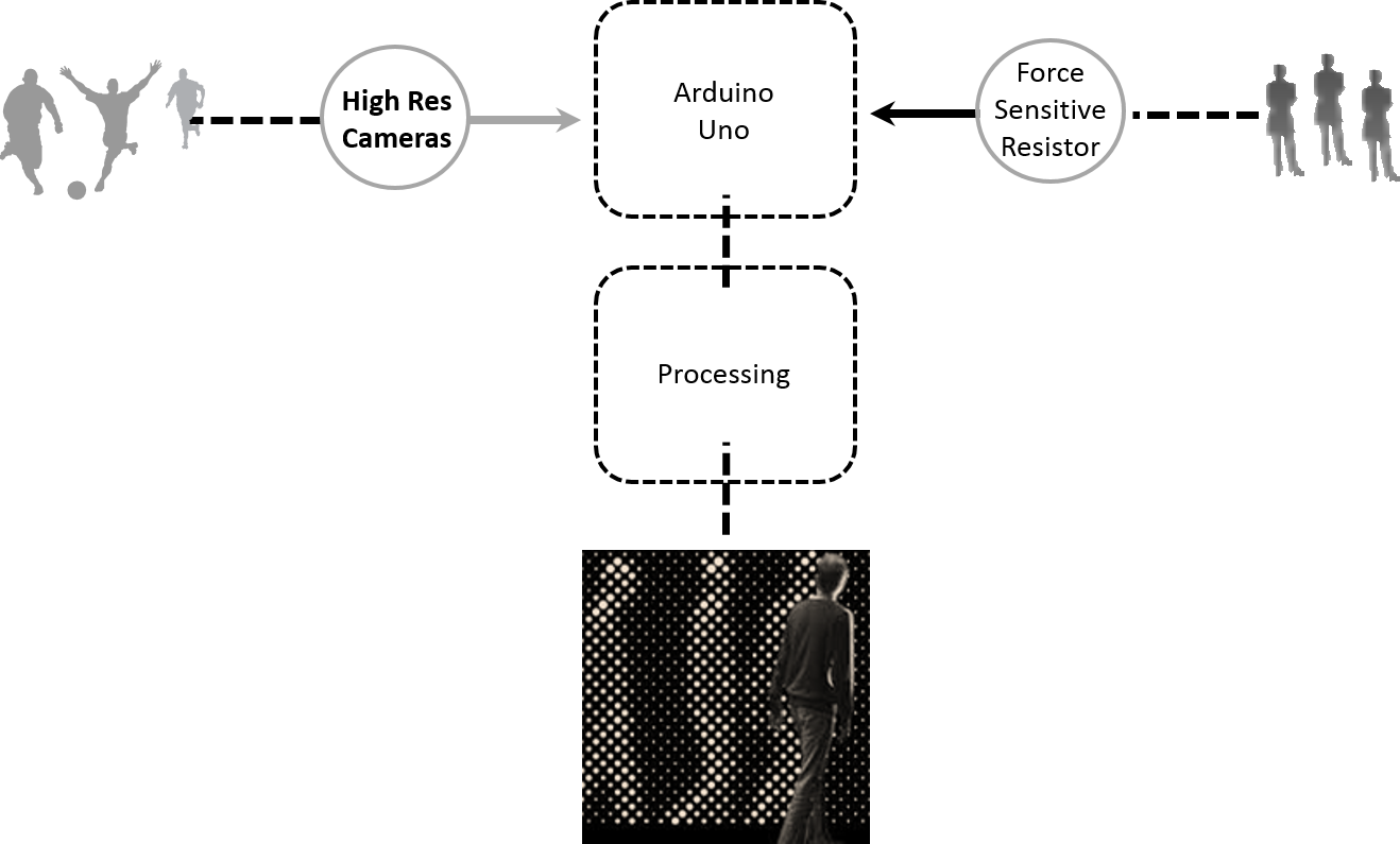
For the final project, the idea is to capture the movement of players with the high resolution cameras which would give the output interactive images on the walls beneath the seating tiers. Also at the same the movement of crowd in the throughway would generate different colored iterations on the interactive wall. The colors would be determined by the activity and crowd in the marketplace and other public spaces under the bridge. The movement of crowd will generate pressure on the floor which would be captured by the force senstive resistors.
TECHNICAL DETAILS :
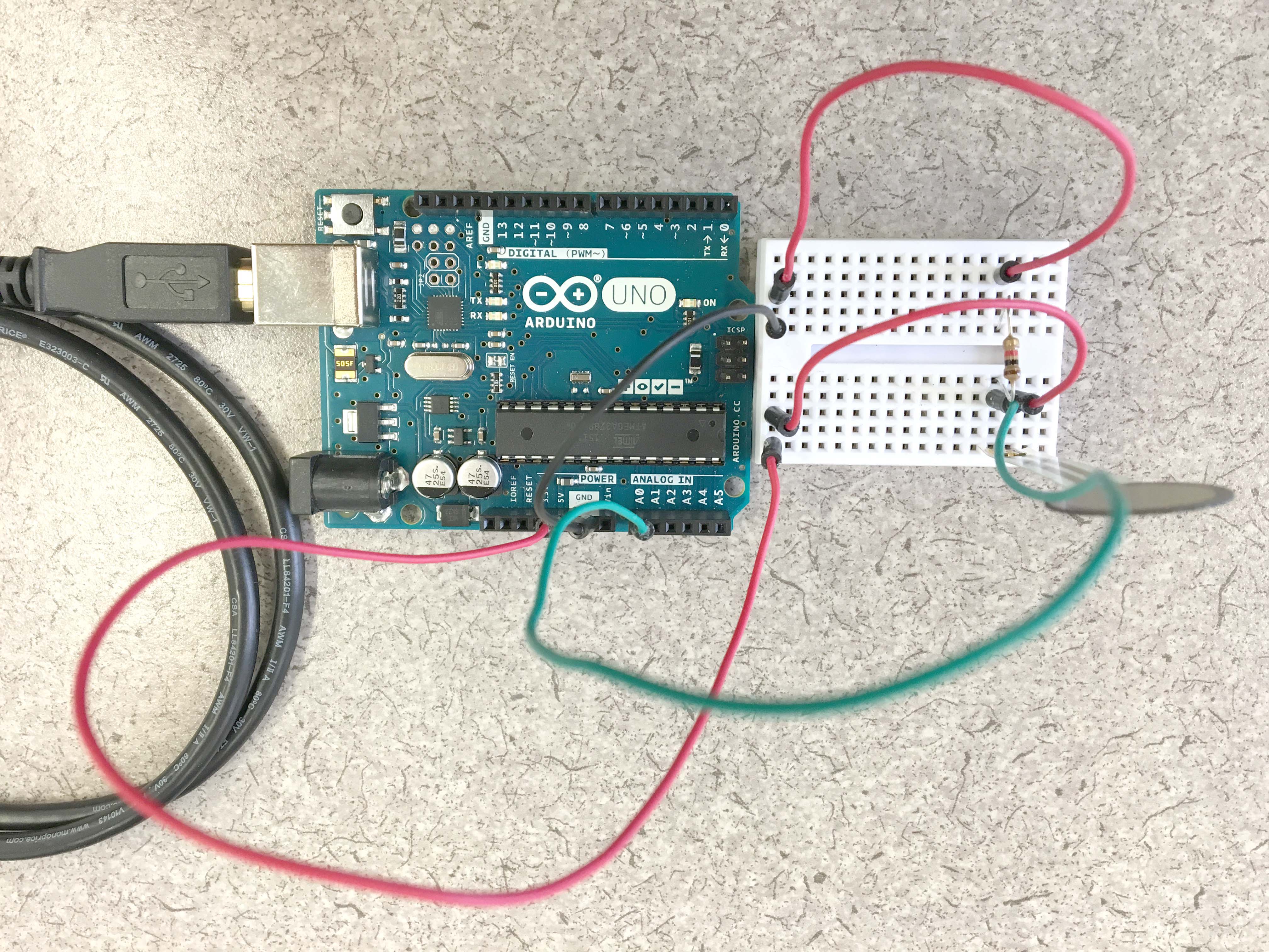
Arduino Uno Assemby –
Force Sensitive Resistor
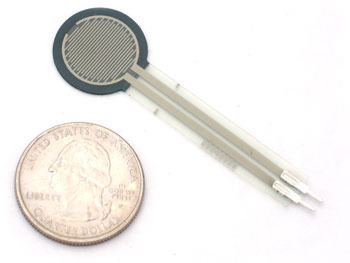
FSRs are sensors that allow you to detect physical pressure, squeezing and weight. They are simple to use and low cost. This is a photo of an FSR, specifically the Interlink 402 model. The 1/2″ diameter round part is the sensitive bit.
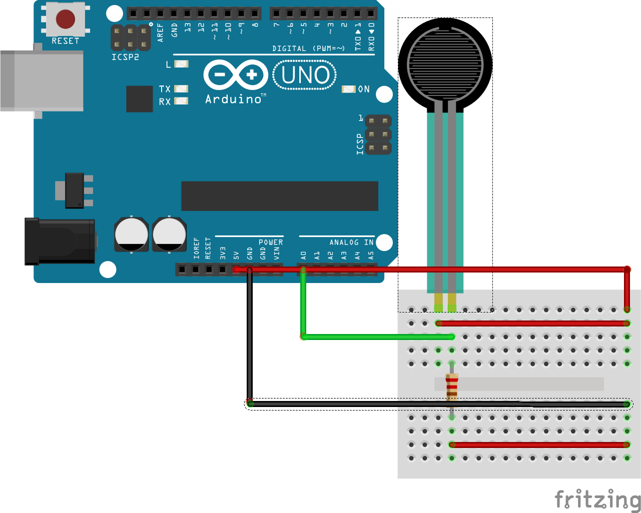
Fritzing Layout –
Process –
Arduino Uno assembly with the Force Sensitive Resistor(FSR) helps to gauge pressure. The details of FSR can be found on – https://www.adafruit.com/products/166
Attaching a High res camera to Processing 2.21 and further connecting the Arduino sketch of FSR to Processing will give the desired output on the screen.
Arduino Sketch –
int fsrPin = 0; // the FSR and 10K pulldown are connected to a0
int fsrReading; // the analog reading from the FSR resistor divider
void setup(void) {
Serial.begin(9600);
}
void loop(void) {
fsrReading = analogRead(fsrPin);
if (fsrReading < 10) {
Serial.println(1);
} else if (fsrReading < 200) {
Serial.println(2);
} else if (fsrReading < 500) {
Serial.println(3);
} else if (fsrReading < 800) {
Serial.println(4);
} else if (fsrReading < 1000){
Serial.println(5);
}
delay(500);
}
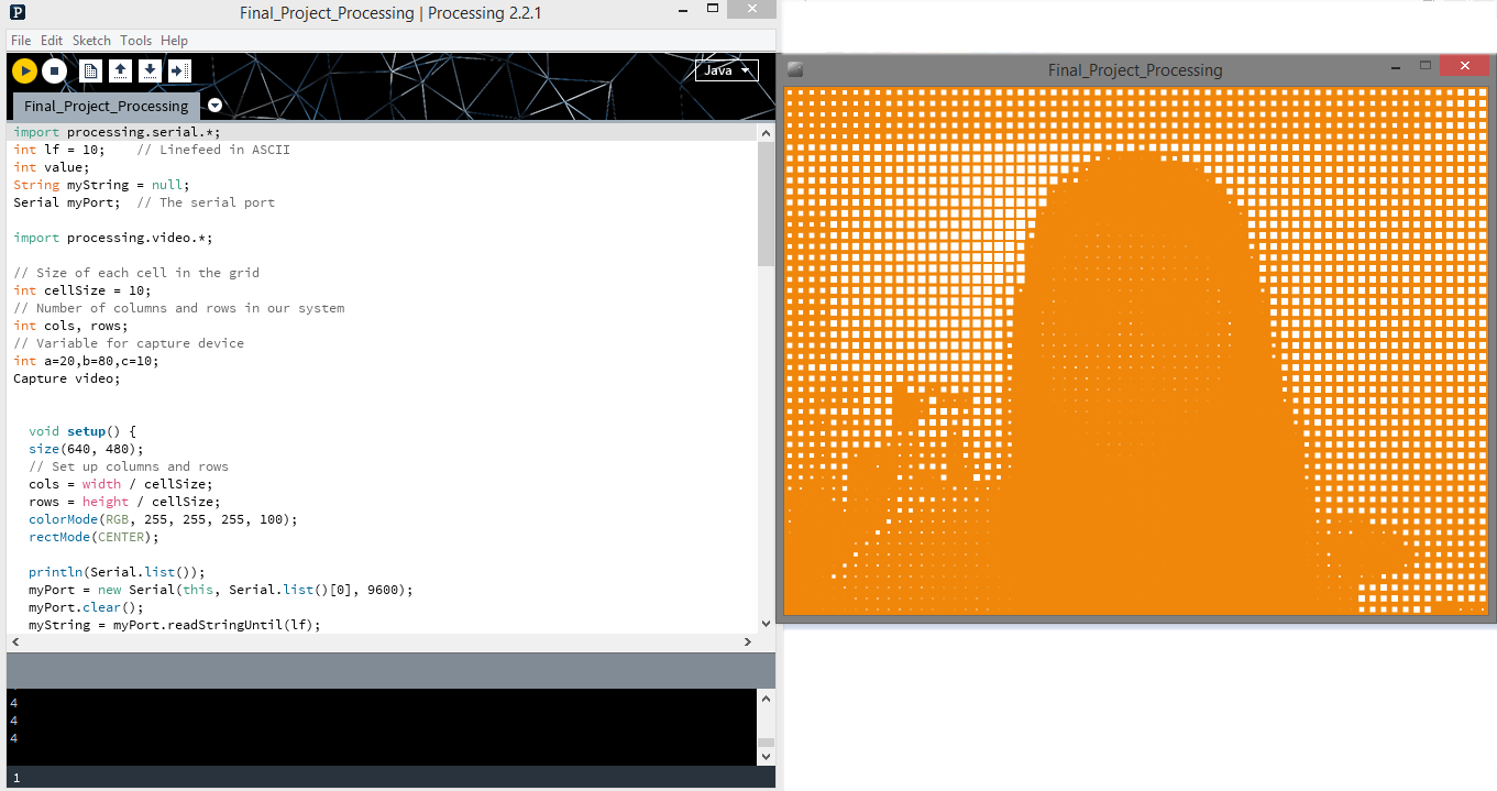
Processing Sketch –
import processing.serial.*;
int lf = 10; // Linefeed in ASCII
int value;
String myString = null;
Serial myPort; // The serial port
import processing.video.*;
// Size of each cell in the grid
int cellSize = 10;
// Number of columns and rows in our system
int cols, rows;
// Variable for capture device
int a=20,b=80,c=10;
Capture video;
void setup() {
size(640, 480);
// Set up columns and rows
cols = width / cellSize;
rows = height / cellSize;
colorMode(RGB, 255, 255, 255, 100);
rectMode(CENTER);
println(Serial.list());
myPort = new Serial(this, Serial.list()[0], 9600);
myPort.clear();
myString = myPort.readStringUntil(lf);
myString = null;
video = new Capture(this, width, height);
video.start();
background(0);
}
void draw() {
if (video.available()) {
video.read();
video.loadPixels();
background(a, b, c);
// Begin loop for columns
for (int i = 0; i < cols;i++) {
// Begin loop for rows
for (int j = 0; j < rows;j++) {
int x = i * cellSize;
int y = j * cellSize;
int loc = (video.width – x – 1) + y*video.width;
color c = video.pixels[loc];
float sz = (brightness(c) / 255.0) * cellSize;
fill(255);
noStroke();
rect(x + cellSize/2, y + cellSize/2, sz, sz);
while (myPort.available() > 0) {
myString = myPort.readStringUntil(lf);
if (myString != null) {
value = int(myString);
if (int( myString.trim() ) == 1 ) {
println(“1”);
a=230;
b=210;
c=215;
}
if (int( myString.trim() ) == 2 ) {
println(“2”);
a=50;
b=180;
c=180;
}
if (int( myString.trim() ) == 3 ) {
println(“3”);
a=230;
b=60;
c=55;
}
if (int( myString.trim() ) == 4 ) {
println(“4”);
a=240;
b=135;
c=90;
}
if (int( myString.trim() ) == 5 ) {
println(“5”);
a=230;
b=230;
c=70;
}
}
}
}
}
}
}
Output –
DESIGN DETAILS –
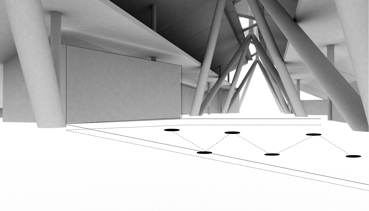
Location of the Interactive wall –
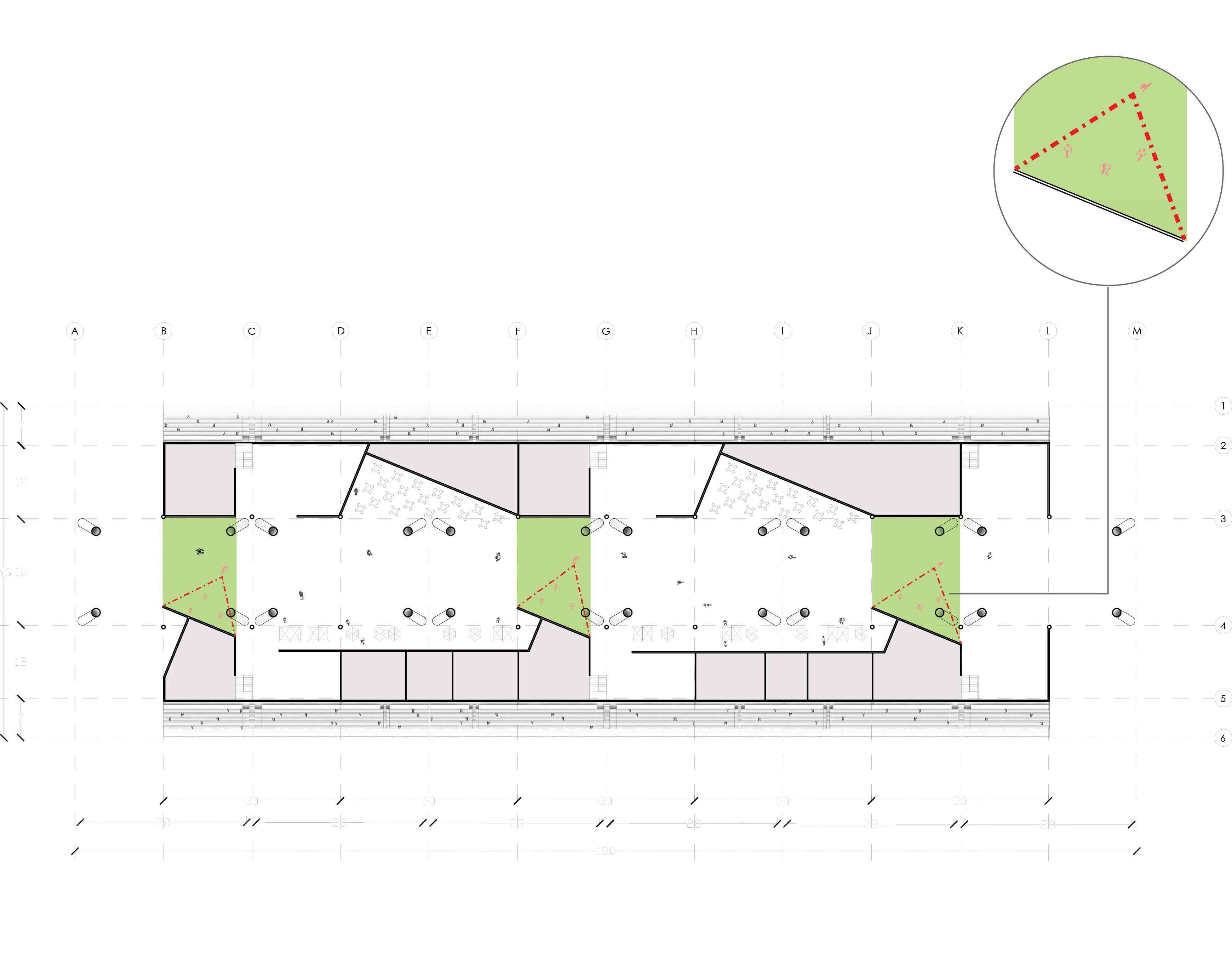
Location of Cams –
Location of Force Sensitive Resistors –
Final Output –
[vsw id=”WWOfSuwJt1c” source=”youtube” width=”700″ height=”340″ autoplay=”no”]