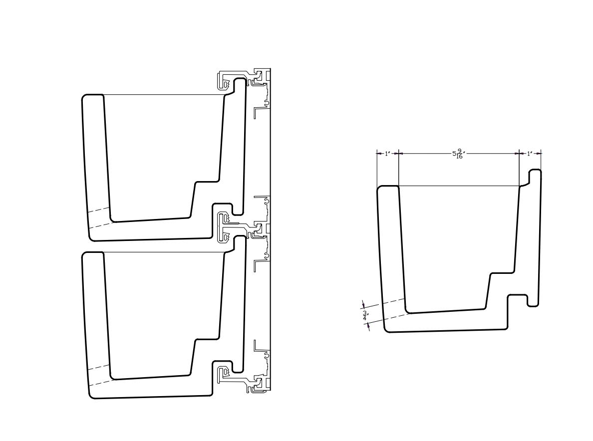
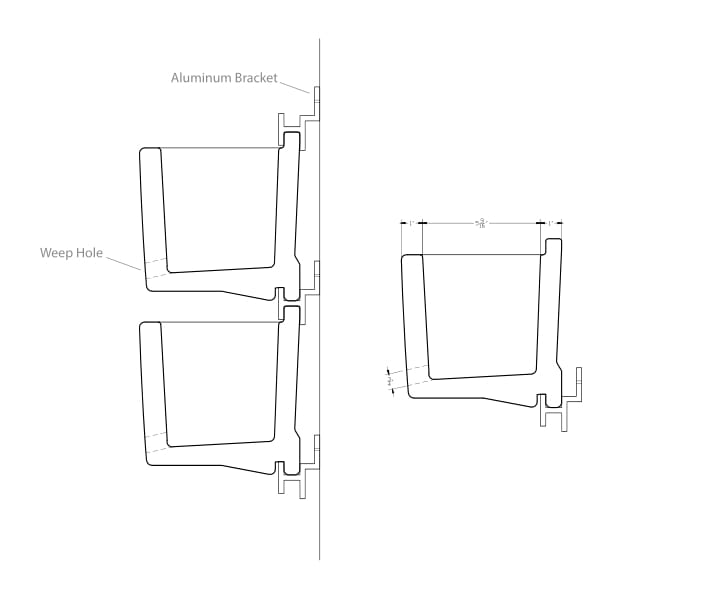
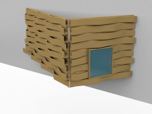
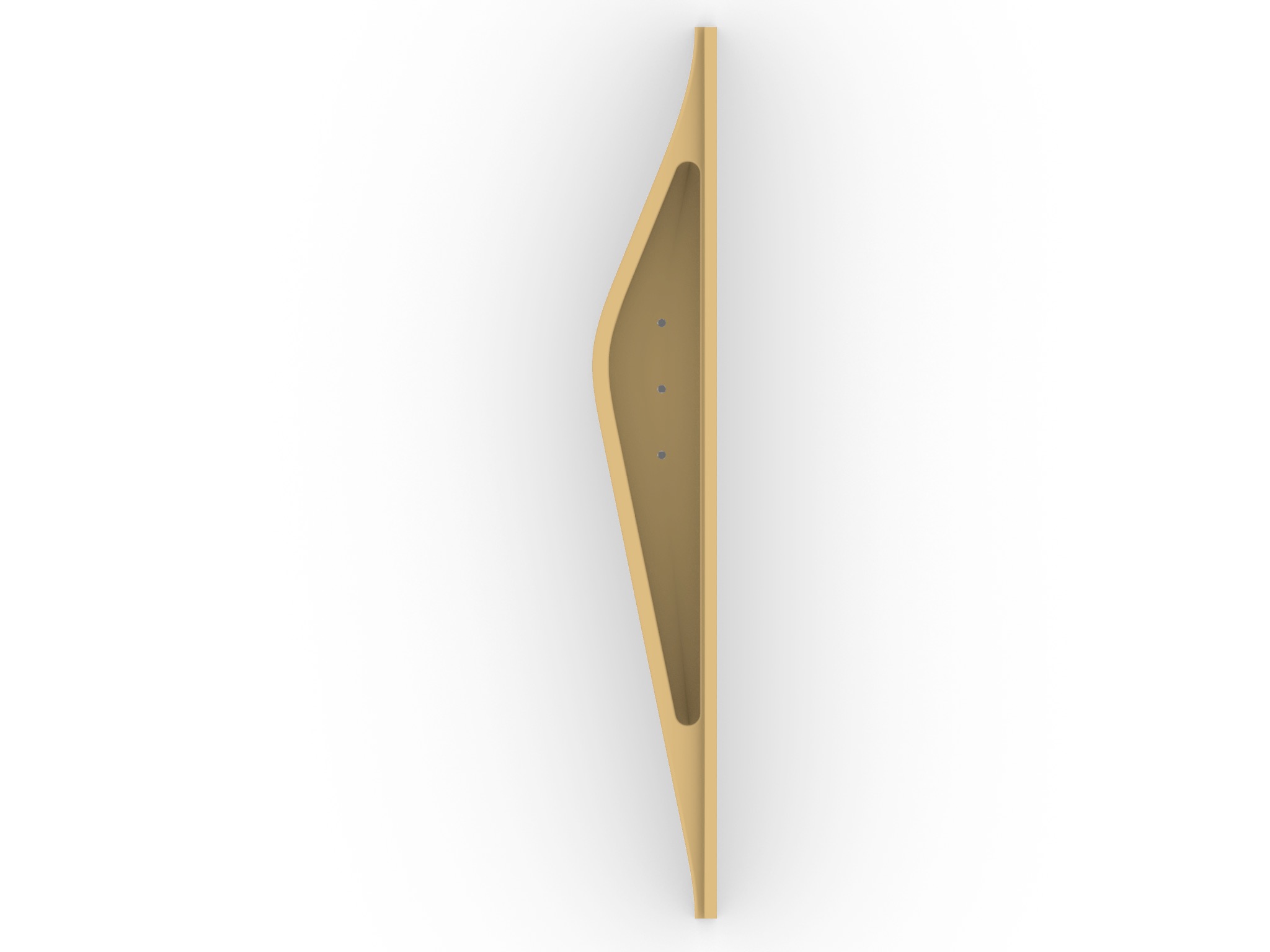
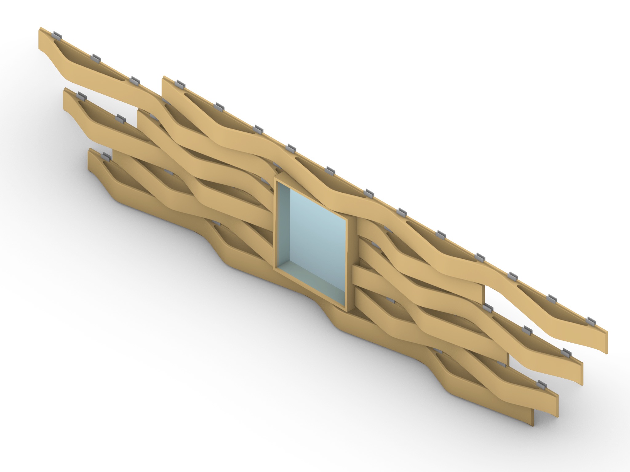
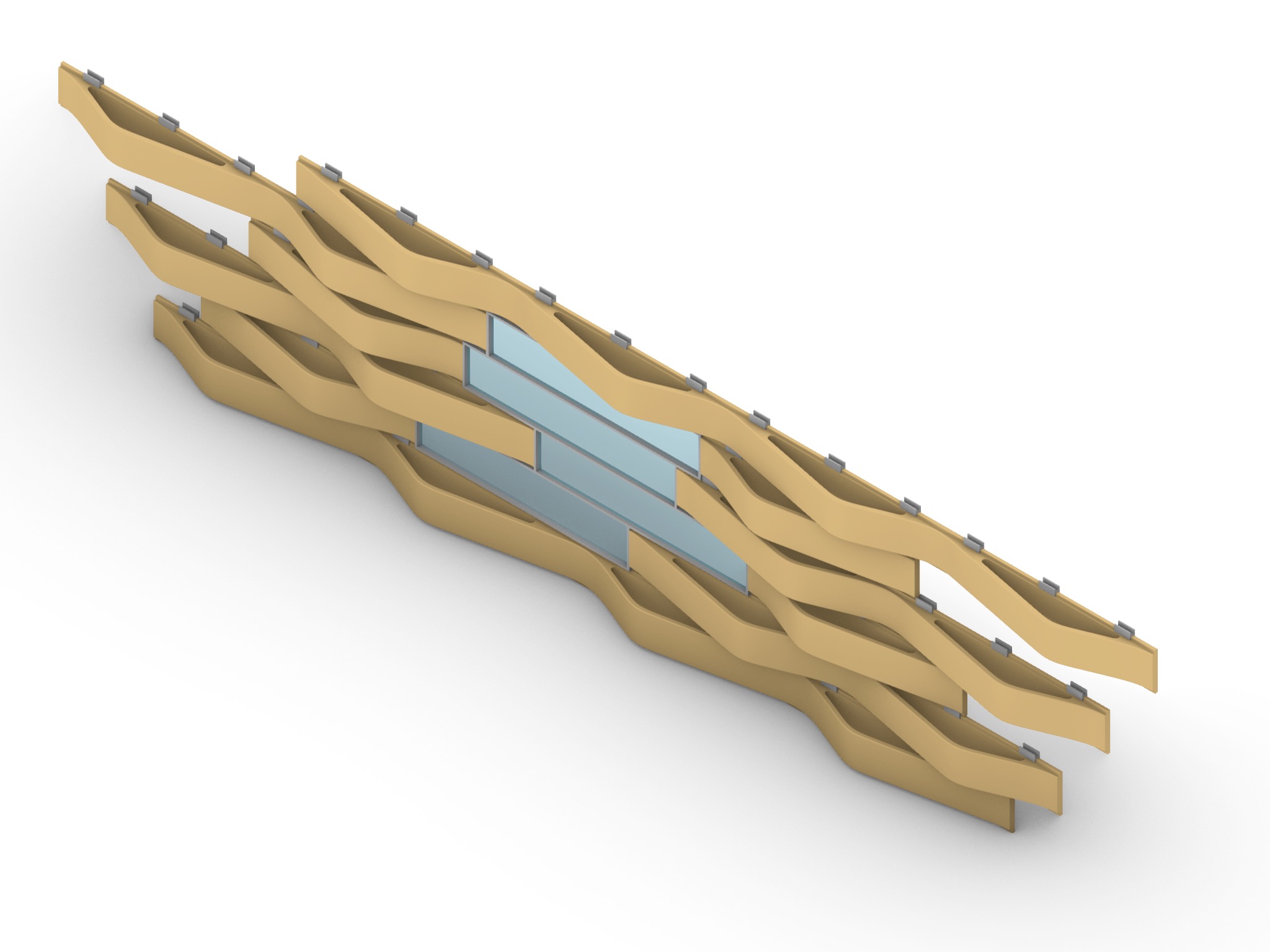
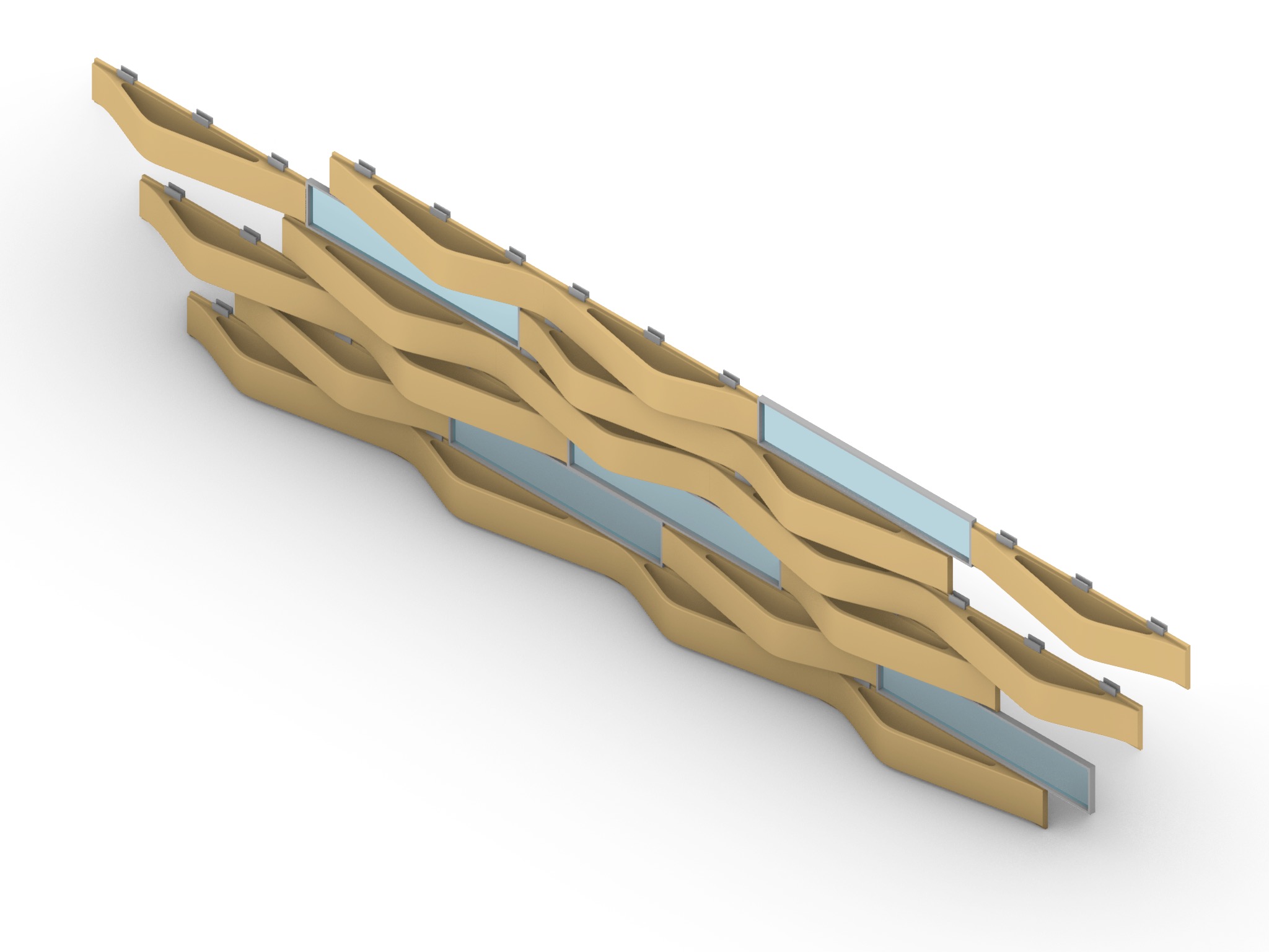
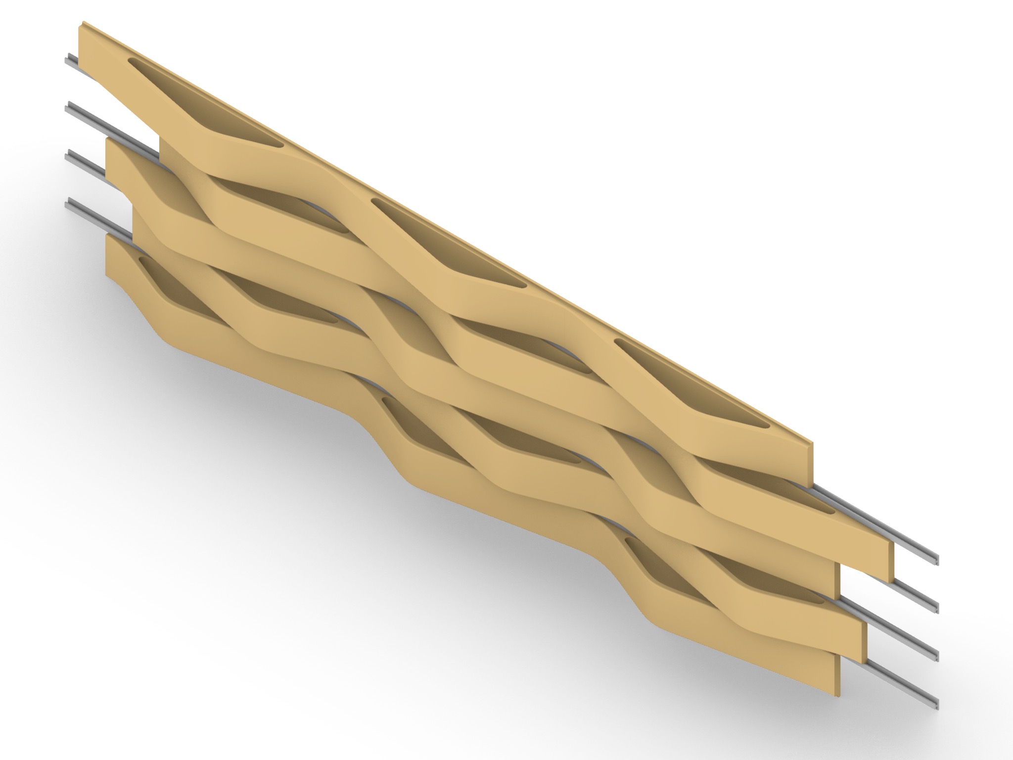
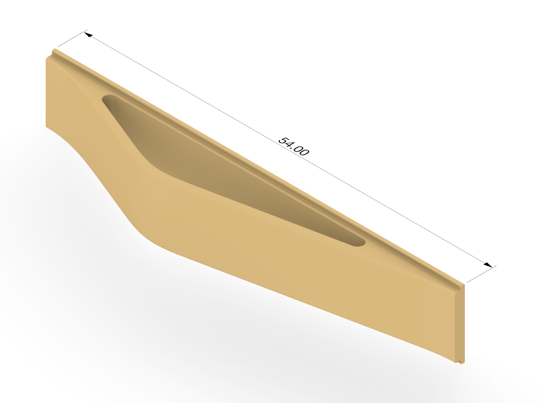
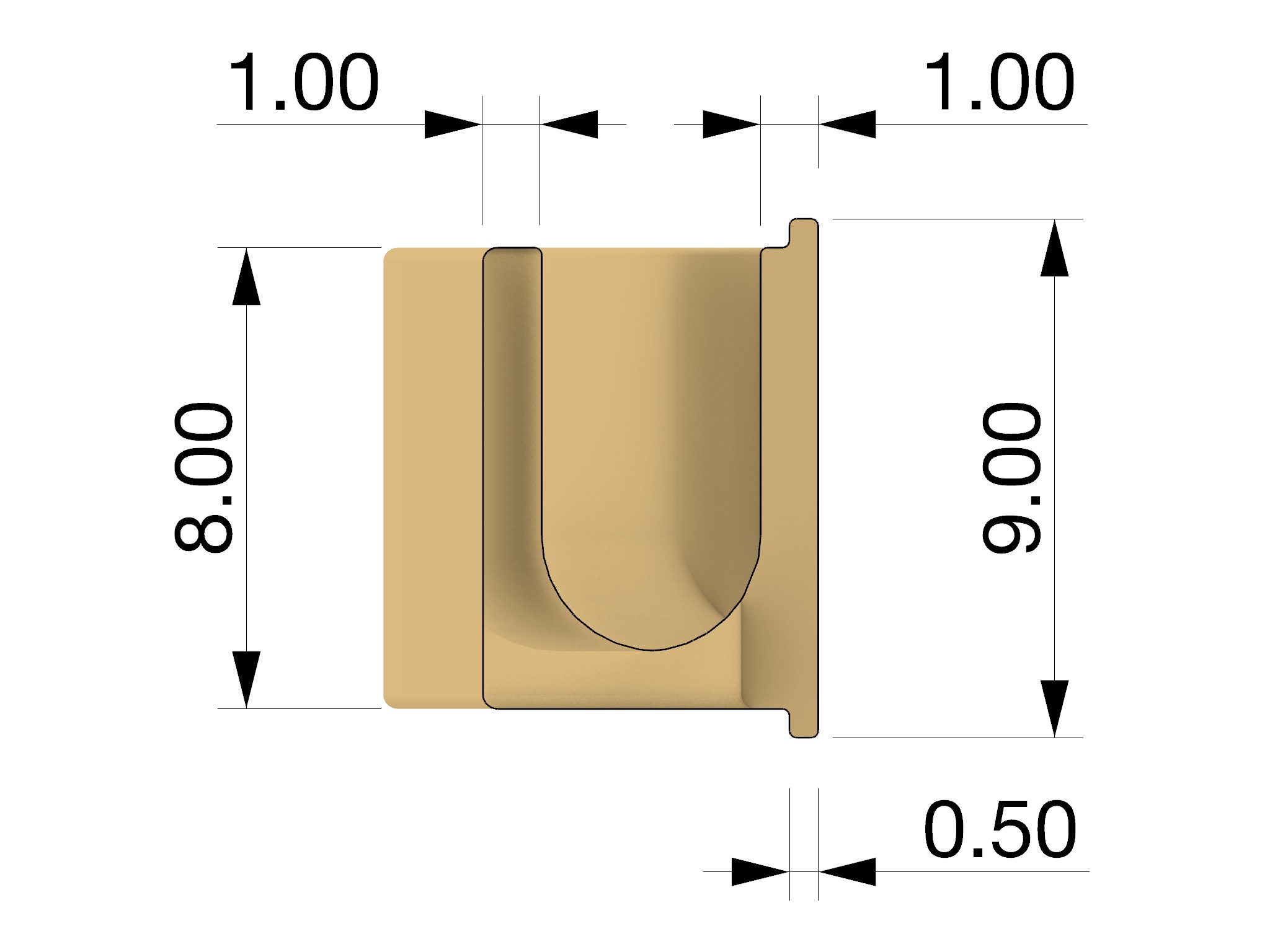
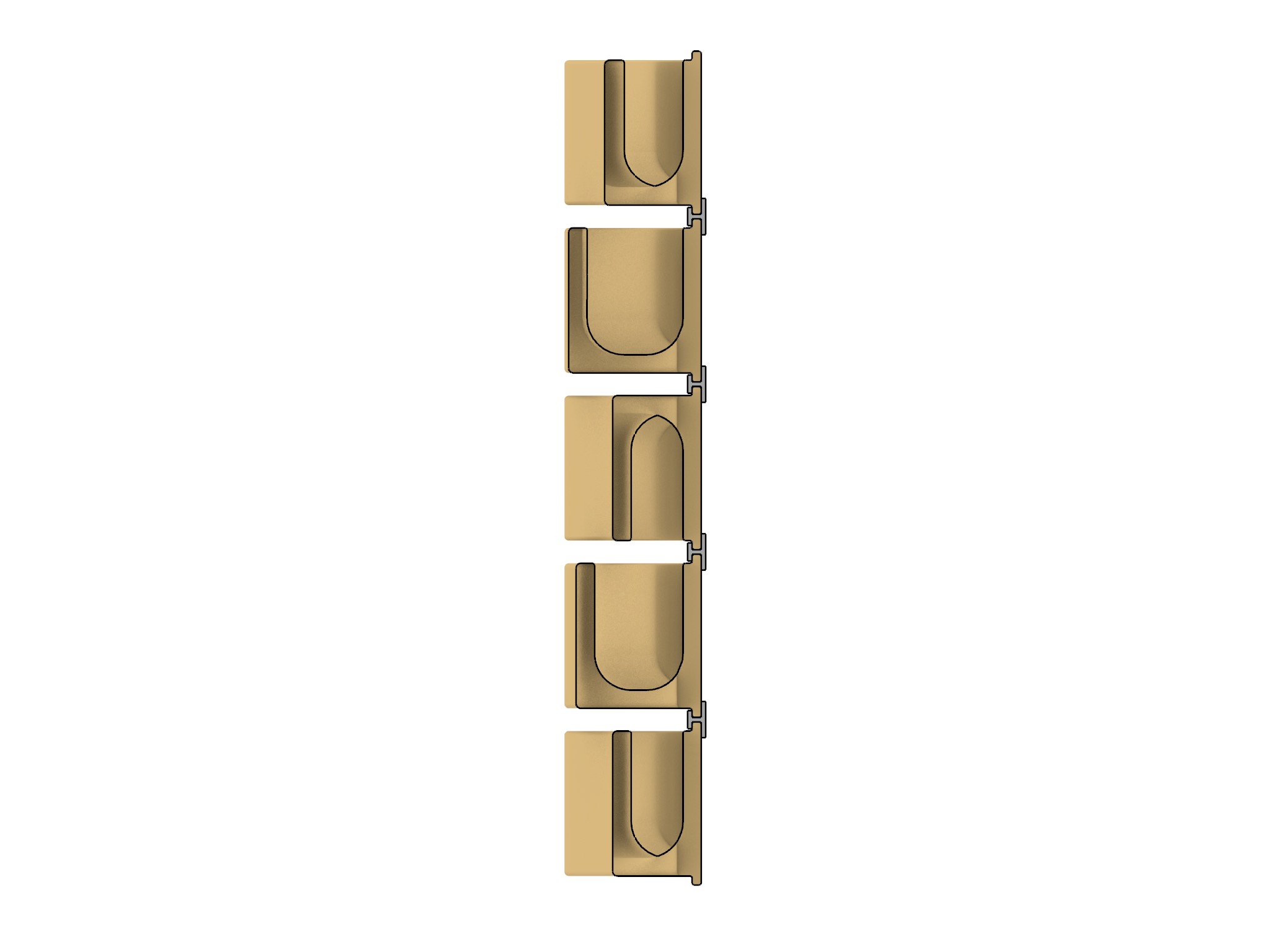
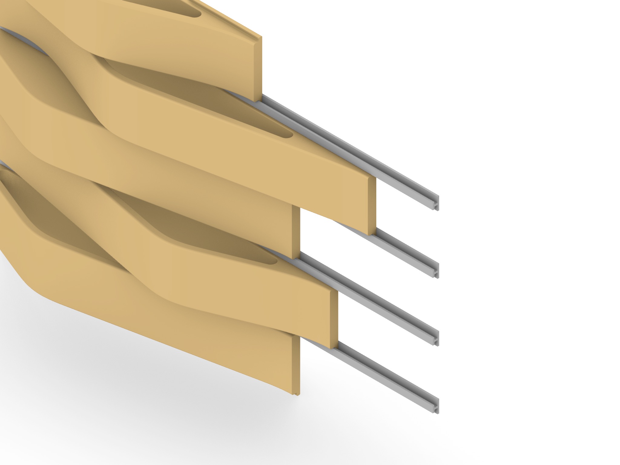
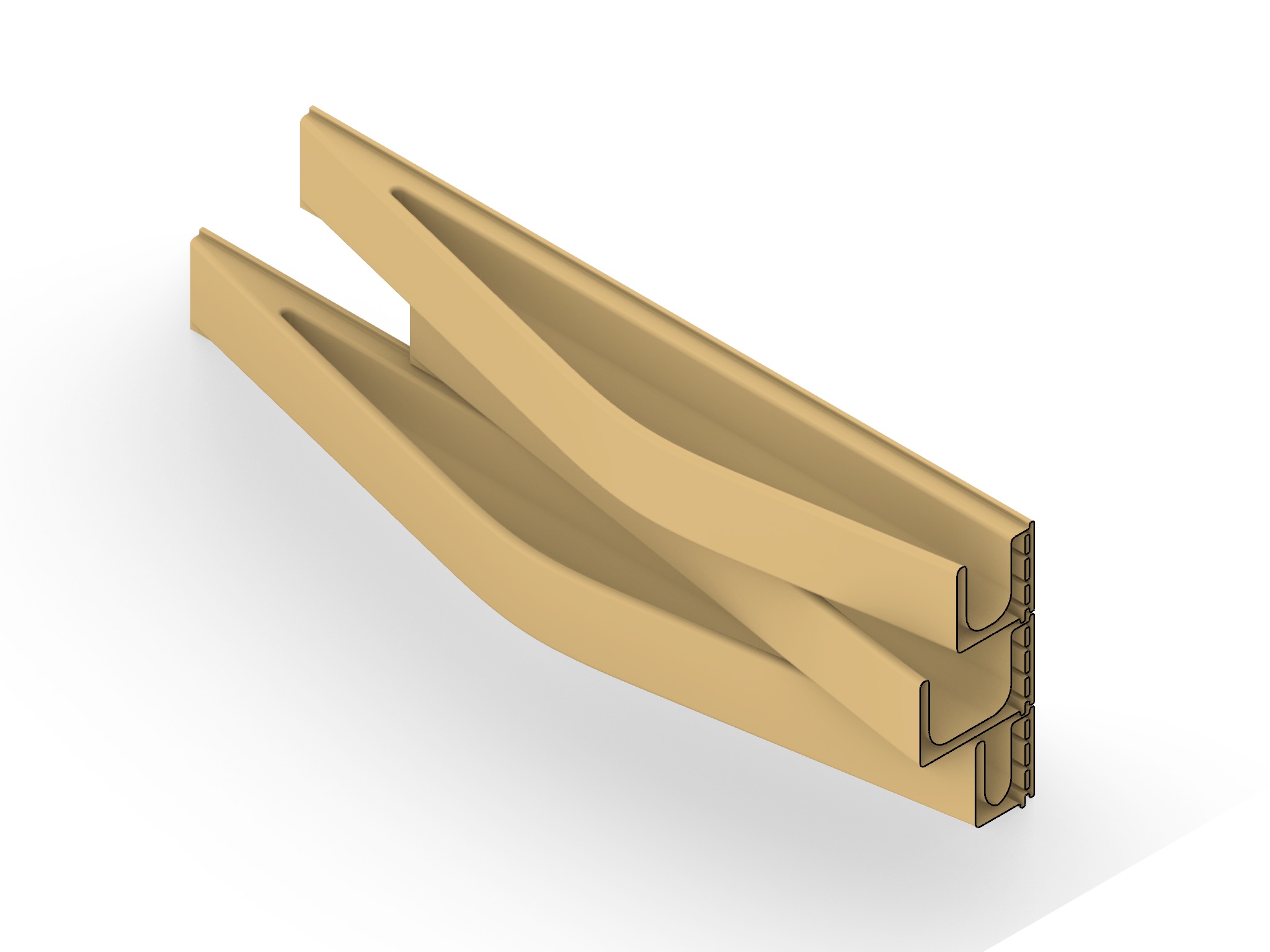
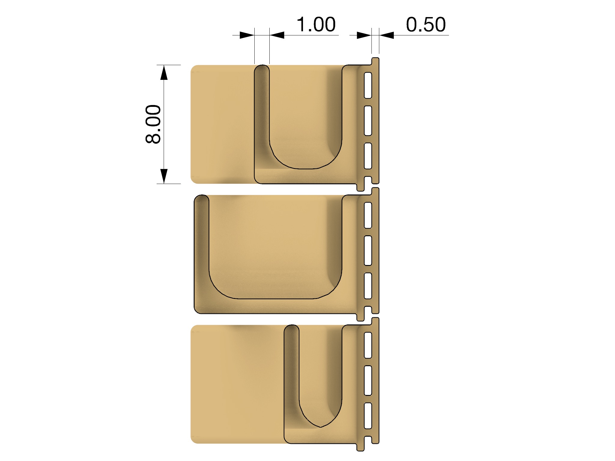
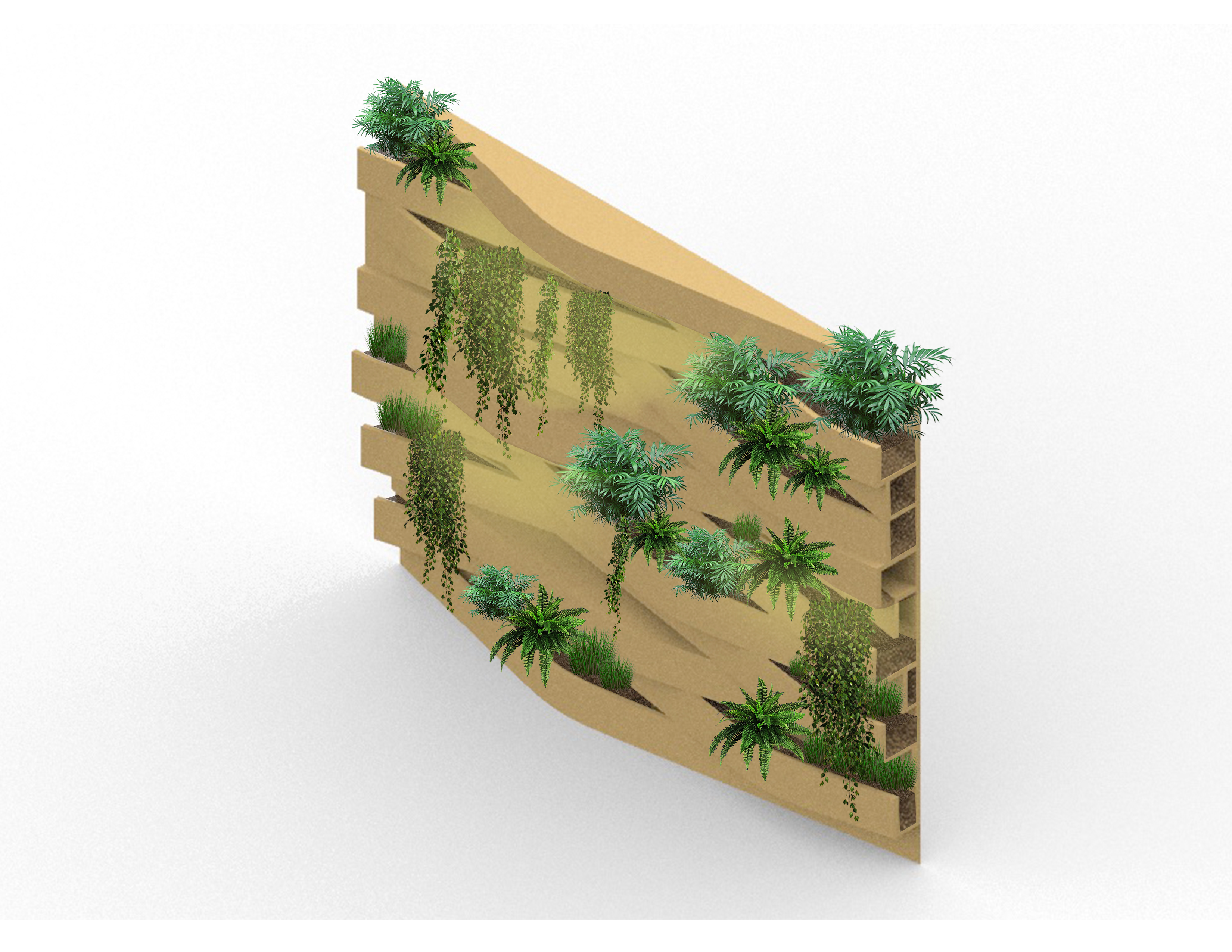
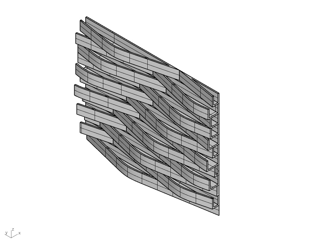
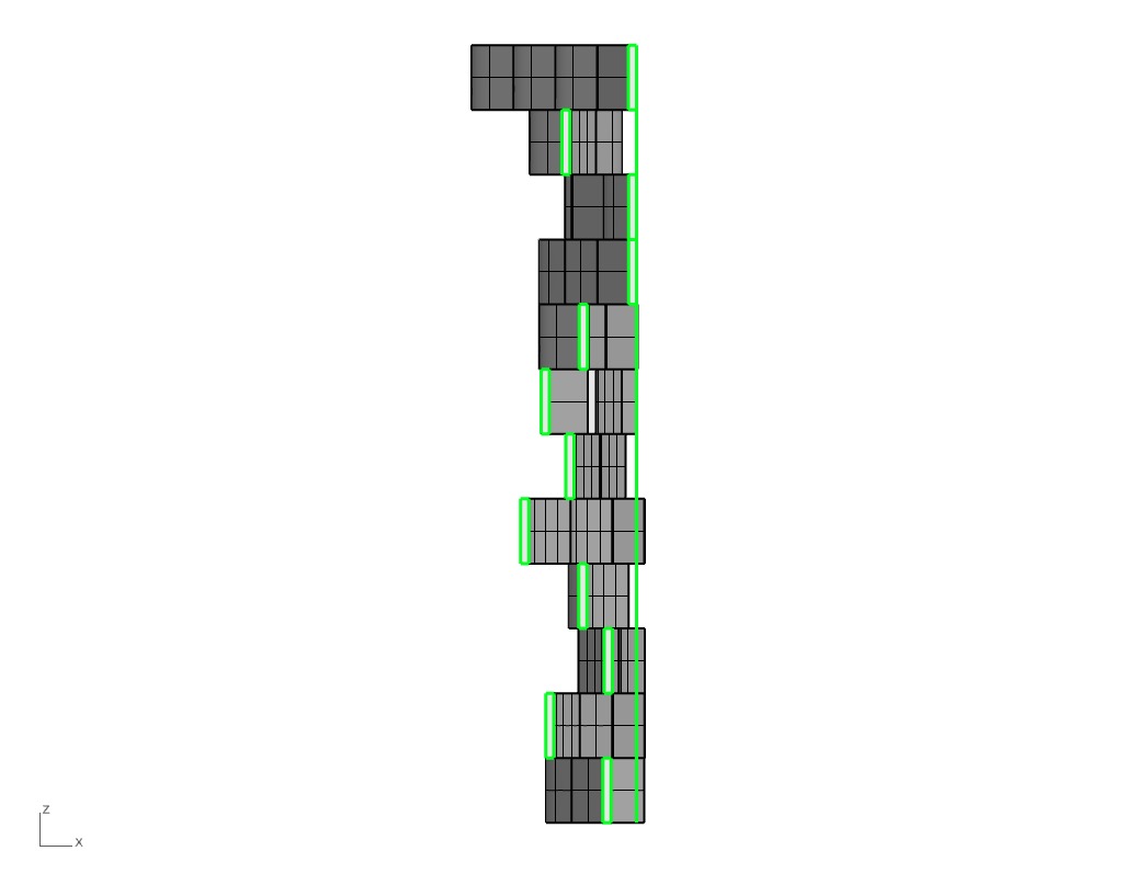
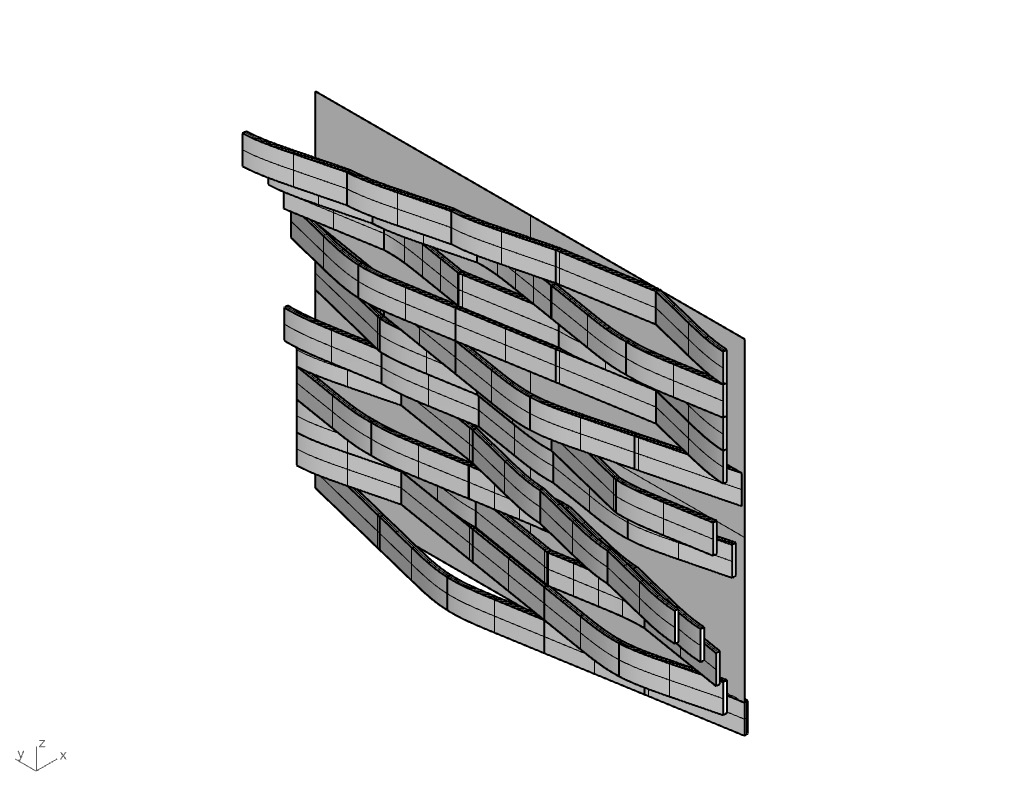
Crevice had many beneficial items that came up durning review. Firstly, the reviewers talked about how the project was successful in handling the “green wall” challenge. Crevice assured a staggered and aesthetic design that functioned well on it’s own even if plants were not growing and there was only dirt siting in the module. Later, the reviewers got into how it would be very difficult to manufacture. They brought up other, more rare techniques that could be used in the manufacturing process rather than our slip cast. Additionally, the lip used to hang the module on the aluminum bracket was a concern. It was not a module that would use the standard mechanism, and in fact needed to be much more simple. Also, our corner condition was met with a bit of unbelievability. The reviewers thought that it was much harder than it looked, and although it was a great way to approach the corner, it would require a lot of precise, on-site work. All in all, the review helped us understand how we could improve Crevice, and explored what was working well with our design and concept. 

In the future of design, we have learned how important it is to be constantly working parallel to the manufacturing end of the process. Architects/designers cannot just come up with ideas and expect them to work without any issues. Of course an idea should be as pure and conceptual as you can get in the beginning phases. However, when it comes time to constructing the project, it must be very meticulously worked out with the manufacturer to assure the vision of the design is met with the greatest ability that it can be. 

The only change we needed to make this week concerned our attachment to the aluminum brackets. We have now update the module to utilize the standard method of attachment used by BVTC.

In this new rendition, the angle of the bottom of the panel was reduced, a lip was placed just before the bracket to prevent water penetration no matter the orientation of the panel, and the space between panels was increased to 3/4 inch.

Updated cross section and mount. The bottom is angled downwards to shed water and hide aluminum fixtures.

example of system used on Gorge project. Single unit.

First shot at slip cast mold.

Possible wall configuration with the new updates.


The overall length has remained the same since last week, yet less aluminum is being used to clip it onto the wall.


The section is relatively unchanged, however, the dimension for the lip has increased from 1/2″x1/2″ to 3/4″x3/4″.


Drainage holes have now been added into the module at it’s lowest points. Ideally, this will prevent plantings from becoming too saturated, and allow an equal distribution of water.


Window Option 1: A punch out window that deals with the edge condition of the planter modules by integrating a piece of terra cotta trim.


Window Option 2A: These windows are the same length and height as the planter modules. This way they can be switched out at any location without having to make cuts to each planter, as they would just fit in the void. Overall, this limits labor cost/time and possibly  looks more integrated with the existing system.


Window Option 2B: Same window method as above, but this is sparsely placing the window. This may give the cracked valley appearance we were going for with “The Gorge”.

Possible wall configuration.

The module has now become smaller in length to fit into the kiln racks. Additionally, we changed the interior corner and widened the diameter so it was not as sharp.

All thicknesses are 1″ (except for the bottom of the planter and lips).

This is our current hanging method. It allows us to be able to flip modules for either the (a) planting or (b) lighting configuration because the lips are symmetrical/mirrored.

We re-designed the curve to work better for the look we wanted. We wanted it to seem continuous when the modules were connected. To achieve this we drew the curve as if it was 3 modules long then cut of the 2 on the ends.

The module has now been set up to have no 90 degree corners. This will help when releasing molds.

This is how the modules will stack.

Additionally, the fact that there are no corners helps with planting. This can be seen in section. Planting will now be easier as dirt removal is easer with curved surfaces.


This scheme uses one curve that is repeated and slightly shifted. However, this time we flipped the members in certain areas. This flipping allows areas for lights to now shine on the facade durning the night

First rendition of the Aluminum production process.

Scheme 1: A repeat of the same element over and over, it is just slightly moved to allow provide a sense of spontaneity.


Scheme 2: The same exact curve as Scheme 1, however it is cut in pieces so that we can make and curve we want. The downside of this is that we have no idea how to hang the pieces because they will all be different distances, and we have no base fo the plants